7.5 - Recovery with an Operating Compressor
Module: Type I Small Appliances
Regulatory verification date: August 11, 2026
Primary authority: Current 40 CFR §§ 82.152, 82.156, and 82.158; current EPA Section 608 Type I test-topic and service-practice guidance
Course role: Explains how an operating appliance compressor can assist system-dependent recovery from a small appliance, why recovery is commonly taken from the high side in this operating-compressor method, how heat or a defrost heater can help move refrigerant, and how to avoid leaving liquid refrigerant trapped in the appliance
Learning Objectives
After completing this section, a student should be able to:
- Explain why an operating appliance compressor is useful during system-dependent recovery.
- Define the relationship between system-dependent recovery equipment and the appliance compressor.
- Explain why EPA’s current Type I test topics require an operative compressor to be operated when using a system-dependent recovery device.
- Describe the conventional high-side recovery method used with an operating small-appliance compressor.
- Explain how the compressor moves refrigerant from the low side toward the high side.
- Explain why one properly located high-side access fitting is often sufficient for this operating-compressor method.
- Explain why the high-side access method is a recovery technique rather than a separate recovery endpoint.
- Explain how controlled heat can increase refrigerant vaporization and improve recovery.
- Explain how a built-in defrost heater can assist recovery from some domestic refrigerators and freezers.
- Explain how cold evaporator surfaces, oil, and low points can retain refrigerant.
- Recognize signs that liquid refrigerant may still be trapped in the appliance.
- Explain why uncontrolled heating or open-flame heating is inappropriate.
- Distinguish an operating-compressor system-dependent setup from a self-contained recovery-machine setup.
- Apply the complete operating-compressor recovery sequence to Type I examination scenarios.
Introduction
A qualifying Type I small appliance contains no more than 5 pounds of refrigerant and is:
fully manufactured at a factory
+
factory charged
+
hermetically sealed at a factory
Because the appliance is factory sealed, service access is often limited.
If the appliance compressor still operates, that compressor can become an important part of the recovery process.
Current 40 CFR §82.152 defines system-dependent recovery equipment as recovery equipment that requires assistance from components contained in the appliance to remove refrigerant.
One of the most important forms of appliance assistance is:
OPERATING APPLIANCE COMPRESSOR
EPA’s current Type I test topics specifically include the:
Need to operate operative compressors
when recovering refrigerant
with a system-dependent ("passive") recovery device
In the conventional Type I training method, the operating compressor moves refrigerant from the low side toward the high side, and refrigerant is recovered through a high-side access connection.
A simple mental picture is:
EVAPORATOR / LOW SIDE
        ↓
operating appliance compressor
        ↓
DISCHARGE / HIGH SIDE
        ↓
high-side access fitting
        ↓
system-dependent recovery equipment
        ↓
recovery container
This section focuses on that method.
The regulatory recovery endpoint itself was established in Section 7.3.
The important distinction is:
Section 7.3
→ HOW FAR recovery must proceed
while:
Section 7.5
→ HOW an operating compressor can help achieve that endpoint
Key Concepts
1. System-Dependent Recovery Uses the Appliance
Current 40 CFR §82.152 defines system-dependent recovery equipment as equipment that requires assistance from components contained in the appliance to remove refrigerant.
Assistance can include:
- Operation of the appliance compressor.
- Refrigerant pressure.
- Pressure differences within the appliance.
- Other appliance components or conditions that move refrigerant.
For the operating-compressor method:
appliance compressor
→ refrigerant-moving force
This is different from a self-contained recovery machine.
A self-contained machine has its own refrigerant-moving capability and does not require assistance from appliance components.
2. Small Appliances Are Within the Ordinary System-Dependent Charge Limit
Current 40 CFR §82.156(e) states that system-dependent equipment may not be used with appliances having a full charge greater than 15 pounds unless the equipment is permanently attached as a pump-out unit.
A Section 608 small appliance contains:
5 lb or less
Therefore:
small appliance
→ below 15-lb system-dependent limit
System-dependent recovery is consequently an important Type I technique.
This does not mean that every Type I service job must use system-dependent equipment.
Self-contained equipment can also be appropriate when:
- It is suitable for the refrigerant.
- It is certified for the application.
- It is used according to manufacturer instructions.
Section 7.7 develops self-contained recovery separately.
3. EPA Specifically Tests Compressor Operation in the System-Dependent Method
EPA’s current Type I test topics identify:
Need to operate operative compressors
when recovering refrigerant
with a system-dependent ("passive") recovery device
This is an important exam fact.
Therefore:
compressor works
+
system-dependent recovery
→ operate the appliance compressor
unless the equipment or appliance manufacturer’s instructions require a different safe procedure.
4. High-Side Recovery Is a Conventional Operating-Compressor Technique
A widely used Type I training method is:
run appliance compressor
+
recover through high side
The appliance compressor:
- Draws lower-pressure refrigerant vapor from the evaporator/low side.
- Compresses that vapor.
- Discharges it into the high side.
- Helps move refrigerant toward the high-side recovery connection.
For many small appliances, this means:
one high-side access fitting
→ often sufficient
when the compressor is functioning and the system-dependent method is used correctly.
This high-side detail is a recovery technique, not a separate federal recovery percentage.
5. “High Side” Means the Compressor Discharge / Condenser Side
For a basic vapor-compression cycle:
evaporator
→ suction line
→ compressor
→ discharge line
→ condenser
→ liquid line
→ metering device
→ evaporator
The high side includes the portion of the refrigeration circuit downstream of the compressor discharge and upstream of the pressure-reducing metering device.
In a small appliance, a high-side access location may be associated with:
- Compressor discharge tubing.
- Condenser-side tubing.
- A manufacturer-provided process tube.
- Another approved high-side access point.
Use the appliance manufacturer’s service information whenever available.
6. The Compressor Does Not “Create Refrigerant”
The compressor changes refrigerant pressure and moves refrigerant.
It does not change the total refrigerant mass.
The purpose during recovery is:
move refrigerant already in appliance
→ toward recovery connection
not:
generate additional refrigerant
7. Recovery Flow Depends on Pressure Difference
Refrigerant moves when a pressure difference exists between the appliance and the recovery destination.
The appliance compressor can help establish that pressure difference.
As refrigerant is removed:
- Appliance pressure falls.
- Remaining liquid may boil.
- Cold regions may retain liquid.
- Recovery rate may decrease.
This is why heat and refrigerant movement become important late in the recovery process.
Why Recover From the High Side With an Operating Compressor?
1. Compressor Flow Direction Helps the Technician
During normal operation, the compressor moves refrigerant from:
LOW SIDE
→
HIGH SIDE
Therefore, when system-dependent recovery is taken from the high side:
compressor pumping direction
+
recovery direction
→ work together
The technician is using the appliance’s normal refrigerant-moving component to assist recovery.
2. The Low Side Is Continuously Drawn Down
As the compressor operates:
evaporator vapor
→ suction line
→ compressor
This tends to remove refrigerant vapor from the low side.
If liquid refrigerant in the evaporator vaporizes, the resulting vapor can also be pulled toward the compressor.
3. The Compressor Pushes Refrigerant Toward the Recovery Point
The compressor discharge sends refrigerant toward:
discharge line
→ condenser / high side
→ high-side access
If the recovery equipment is connected appropriately, the high-side connection becomes the outlet path for refrigerant leaving the appliance.
4. One High-Side Access Point Is Often Enough
Secondary Type I training guidance commonly states that one high-side access fitting is normally enough when:
- The compressor is operating.
- The refrigeration circuit is intact.
- Refrigerant can move through the appliance.
- The access point is correctly located.
- The system-dependent equipment is properly connected.
The reason is:
operating compressor
→ moves refrigerant from low side to high side
This should not be turned into an absolute rule.
Additional access may be required if:
- Manufacturer instructions require it.
- The appliance configuration prevents effective refrigerant movement.
- A restriction prevents circulation.
- The compressor does not actually operate.
- The chosen recovery equipment requires another connection.
5. Do Not Confuse This With the Failed-Compressor Procedure
For a failed compressor:
compressor cannot move refrigerant
Therefore the technician may need:
high-side access
+
low-side access
and additional methods to mobilize trapped refrigerant.
That procedure belongs to:
Section 7.6 - Recovery with a Failed Compressor.
Refrigerant Movement During Operating-Compressor Recovery
1. Refrigerant Starts in Multiple Locations
Before recovery begins, refrigerant may exist as:
- Vapor in the evaporator.
- Vapor in the suction line.
- Vapor in the compressor shell.
- High-pressure vapor in the discharge line.
- Liquid/vapor mixture in the condenser.
- Liquid in the liquid line.
- Refrigerant dissolved in compressor oil.
- Liquid trapped in cold low points.
The recovery procedure must eventually remove enough refrigerant to satisfy the applicable recovery endpoint.
2. The Compressor Provides Continuous Circulation
When the compressor operates:
low-side vapor
→ compressor suction
→ compression
→ high-side discharge
This helps reduce the amount of refrigerant remaining on the low side.
3. Liquid Must Become Movable
A compressor is primarily designed to compress vapor.
Liquid refrigerant trapped in the evaporator cannot simply be compressed as a liquid.
For liquid to move effectively through the normal compressor flow path, it generally needs to:
absorb heat
→ boil / vaporize
→ flow toward compressor
This is why warming a cold evaporator can improve recovery.
4. Avoid Liquid Floodback
The operating compressor should not be deliberately flooded with liquid refrigerant.
Liquid entering a compressor can cause:
- Liquid slugging.
- Oil dilution.
- Mechanical damage.
- Abnormal compressor operation.
The objective is:
vaporize trapped liquid
→ move vapor safely
not:
force large amounts of liquid into compressor suction
5. Capillary-Tube Systems Can Affect Refrigerant Movement
Many small appliances use a capillary tube.
The capillary tube creates a large pressure drop during normal operation.
As the compressor operates during recovery:
- Low-side pressure can decrease.
- High-side refrigerant moves toward the recovery connection.
- Refrigerant trapped on the low side must vaporize and pass through the compressor flow path.
- Pressure differences can change as the charge becomes smaller.
Do not assume that all small appliances have the same tubing arrangement.
Heat Application Where Appropriate
1. Why Heat Can Speed Recovery
Heating refrigerant generally increases its tendency to vaporize and increases saturation pressure.
Therefore controlled heat can help:
trapped liquid refrigerant
→ vaporize
→ move through system
→ reach recovery connection
This is especially useful when refrigerant remains in a cold:
- Evaporator.
- Freezer compartment.
- Suction line.
- Oil-containing region.
- Low point.
2. Heat Should Be Controlled
The correct principle is:
controlled heat
→ assist vaporization
not:
maximum heat
→ faster is always better
Too much heat can:
- Damage wiring.
- Damage plastic parts.
- Damage insulation.
- Raise refrigerant pressure excessively.
- Create ignition hazards with flammable refrigerants.
- Damage appliance components.
3. Never Use an Open Flame as a General Recovery Heating Method
Do not use an open flame to warm a charged appliance during recovery.
High temperatures can:
- Decompose refrigerant.
- Produce hazardous decomposition products.
- Ignite flammable refrigerant.
- Damage components.
- Create uncontrolled pressure.
Use only a safe heat source appropriate to:
- Refrigerant.
- Appliance.
- Recovery method.
- Manufacturer instructions.
4. Natural Warming Can Help
If the evaporator is extremely cold, allowing it to warm toward room temperature can help remaining liquid refrigerant boil.
This may be preferable to adding external heat when:
- Time permits.
- Manufacturer instructions do not call for another method.
- Safety conditions favor passive warming.
5. Controlled External Heat Can Be Appropriate
Depending on the appliance and approved service procedure, controlled heat may be applied to:
- Evaporator area.
- Refrigerant-containing component.
- Appropriate tubing region.
The purpose is to:
mobilize refrigerant
not to:
heat the appliance indiscriminately
No universal temperature should be memorized for this Type I method.
Defrost Heater
1. Why a Defrost Heater Can Help
Many domestic refrigerators and freezers have an electric defrost heater located near the evaporator.
Its normal purpose is to melt frost from the evaporator.
During an appropriate recovery procedure, that heater can also add heat to the evaporator.
The effect is:
defrost heater ON
→ evaporator warms
→ trapped liquid refrigerant vaporizes more readily
→ compressor can move vapor toward high side
→ recovery can proceed faster
2. This Is a Technique, Not a Federal Recovery Endpoint
Do not confuse:
operate defrost heater
with:
80% / 90% / 4 in. Hg vacuum
The first is a technique.
The second is the required recovery endpoint from Section 7.3.
3. Use the Heater Only When Appropriate
The defrost heater should be used only when:
- The appliance actually has one.
- The heater circuit is intact.
- The service procedure permits its use.
- The refrigerant and appliance safety conditions are understood.
- Manufacturer instructions are followed.
Do not bypass safety controls or improvise wiring merely to energize a heater.
4. The Heater Does Not Replace Compressor Operation
For the operating-compressor system-dependent method:
compressor
→ moves refrigerant
while:
defrost heater
→ helps vaporize trapped liquid
They perform different functions.
5. A Defrost Heater Can Be Most Helpful in the Evaporator Region
Refrigerant may remain liquid in a cold evaporator even after much of the charge has been removed.
By warming the evaporator:
remaining liquid
→ boils
→ becomes vapor
→ is drawn toward compressor
This reduces the chance that refrigerant remains trapped simply because the evaporator is cold.
Avoiding Trapped Liquid
1. Why Liquid Becomes Trapped
Liquid refrigerant may remain in:
- Evaporator tubing.
- Low points in piping.
- Oil.
- Accumulators, where present.
- Cold heat-exchanger sections.
- Sections isolated by restrictions.
As pressure drops, liquid should tend to boil, but boiling requires heat.
If the surrounding metal and air are very cold, vaporization can become slow.
2. A Temporary Pressure Drop Does Not Always Mean All Refrigerant Is Gone
During recovery, pressure may fall because:
- Vapor has been removed quickly.
- Remaining liquid is still cold.
- Liquid has not yet boiled.
- Refrigerant is dissolved in oil.
If recovery is stopped, remaining refrigerant can:
absorb heat
→ vaporize
→ pressure rises again
This is sometimes called pressure rebound.
Although the current EPA Type I test-topic page does not specify a fixed rebound waiting period, the physical principle is important:
A low pressure reading by itself does not prove that all remaining liquid refrigerant has been removed.
3. Use Heat to Mobilize, Not to Overpressure
The objective is:
warm cold refrigerant enough to vaporize
while avoiding:
- Excessive pressure.
- Component damage.
- Ignition hazard.
- Refrigerant decomposition.
4. Keep Refrigerant Moving Toward the High Side
With the compressor operating:
low-side vapor
→ compressor
→ high side
→ recovery connection
A correctly located high-side recovery path helps prevent refrigerant from repeatedly circulating through the entire refrigeration circuit.
5. Do Not Intentionally Trap Liquid Between Closed Valves
A sealed section containing liquid refrigerant can experience a large pressure rise if the liquid warms and expands.
Avoid creating an isolated liquid-filled section without considering thermal expansion.
This is especially important when:
- Closing service valves.
- Disconnecting hoses.
- Isolating fittings.
- Heating nearby tubing.
Operating-Compressor System-Dependent Recovery Setup
Basic Concept
A simplified Type I system-dependent arrangement is:
LOW SIDE / EVAPORATOR
        ↓
OPERATING APPLIANCE COMPRESSOR
        ↓
HIGH SIDE / CONDENSER
        ↓
HIGH-SIDE ACCESS FITTING
        ↓
SYSTEM-DEPENDENT RECOVERY CONNECTION
        ↓
APPROPRIATE RECOVERY CONTAINER / EQUIPMENT
The appliance compressor supplies the refrigerant-moving work.
Important Distinction
Do not draw or imagine:
recovery-machine compressor
as the main refrigerant-moving device in this section.
That would be:
self-contained recovery
and belongs primarily to Section 7.7.
Recovery Container
Secondary Type I training materials commonly describe a system-dependent/passive setup in which refrigerant is captured in a suitable nonpressurized recovery container as part of the approved system-dependent equipment configuration.
The exact container and connection arrangement must follow:
- Recovery-equipment instructions.
- Equipment certification.
- Refrigerant compatibility.
- Applicable safety requirements.
Do not improvise with an ordinary disposable refrigerant cylinder.
Step-by-Step Recovery Procedure
Step 1 — Confirm That the Appliance Is Type I
Verify:
factory manufactured
+
factory charged
+
factory hermetically sealed
+
≤ 5 lb refrigerant
Step 2 — Identify the Refrigerant
Confirm the refrigerant from:
- Nameplate.
- Manufacturer information.
- Appropriate pressure-temperature identification procedure when necessary.
Do not mix refrigerants in recovery equipment or containers.
Step 3 — Confirm the Compressor Operates
Do not assume:
appliance is not cooling
→ compressor is failed
Determine whether the compressor can actually operate.
If the compressor is nonfunctional, use the Section 7.6 method instead.
Step 4 — Select Appropriate Recovery Equipment
Verify:
- System-dependent equipment is appropriate.
- Equipment is certified as required.
- Equipment is compatible with the refrigerant.
- Hose and fitting materials are appropriate.
- The recovery container is correct for the specific equipment.
Step 5 — Determine the Required Recovery Endpoint
Refer to Section 7.3.
For example, with recovery equipment manufactured on or after November 15, 1993 and a functioning appliance compressor, the percentage method requires:
90% recovery
The separate:
4 in. Hg vacuum
alternative remains available under the current small-appliance rule.
Do not confuse the procedure with the endpoint.
Step 6 — Locate the High-Side Access Point
Use:
- Manufacturer process stub.
- Approved high-side access point.
- Appropriate temporary access fitting when needed.
Review:
Section 7.4 - Access Fittings and Process Stubs.
Step 7 — Prepare the Recovery Connection Before Opening Access
Have the complete recovery path ready before opening the refrigerant circuit.
This minimizes avoidable emissions.
Step 8 — Connect the Recovery Equipment
Follow the recovery-equipment manufacturer’s instructions.
For the conventional operating-compressor system-dependent method:
high-side access
→ recovery hose / system-dependent equipment
→ appropriate recovery container
Step 9 — Operate the Appliance Compressor
EPA’s current Type I test topics specifically expect the operative compressor to be operated when using system-dependent recovery.
The compressor should now:
pull vapor from low side
→ compress vapor
→ discharge toward high side
Step 10 — Monitor Refrigerant Movement
Watch for:
- Recovery flow.
- Appliance pressure.
- Container condition.
- Hose condition.
- Abnormal compressor sound.
- Frost or cold spots indicating possible remaining liquid.
Step 11 — Apply Heat Where Appropriate
If recovery slows because the evaporator remains very cold:
- Allow natural warming.
- Use an approved controlled heat method.
- Operate the built-in defrost heater if appropriate and allowed.
The purpose is:
vaporize trapped liquid
Step 12 — Avoid Liquid Floodback
Do not deliberately force liquid refrigerant into the compressor suction.
The compressor should primarily receive vapor.
Step 13 — Continue Until the Required Endpoint Is Achieved
Do not stop merely because refrigerant flow becomes slow.
Confirm the applicable requirement from Section 7.3.
Step 14 — Isolate and Stop Equipment Safely
Follow:
- Appliance instructions.
- Recovery-equipment instructions.
- Correct valve sequence.
Step 15 — Manage Refrigerant Remaining in Hoses
Use low-loss connections and the equipment’s approved method to minimize refrigerant release during disconnection.
Step 16 — Remove Temporary Solderless Access Fitting
As discussed in Section 7.4:
temporary solderless access fitting
→ remove at conclusion of service
when it is a temporary device.
Step 17 — Reseal and Leak Check
Complete the service by:
reseal tubing
→ leak check
→ verify final integrity
Recovery Flow Example
Consider a household refrigerator with:
- Functional compressor.
- Capillary-tube metering device.
- High-side process stub.
- Manufacturer-installed defrost heater.
A simplified recovery sequence is:
1. Install approved high-side access fitting.
2. Connect system-dependent recovery equipment.
3. Start appliance compressor.
4. Compressor draws low-side vapor from evaporator.
5. Compressor discharges vapor toward condenser/high side.
6. Refrigerant exits through high-side recovery connection.
7. Evaporator becomes increasingly cold.
8. Recovery flow slows as liquid remains trapped in cold evaporator.
9. Operate defrost heater if appropriate.
10. Evaporator warms.
11. Remaining liquid vaporizes.
12. Compressor moves vapor toward high side.
13. Continue until required recovery endpoint is verified.
The important idea is:
COMPRESSOR
→ moves refrigerant
and:
HEAT
→ helps trapped liquid become movable vapor
Operating Compressor Versus Failed Compressor
| Recovery Feature | Operating Compressor | Failed Compressor |
|---|---|---|
| Appliance compressor can assist recovery | Yes | No |
| System-dependent compressor operation | Run compressor | Impossible |
| Common access strategy | High-side access often sufficient | High + low access often needed |
| Refrigerant-moving force | Appliance compressor + pressure difference | Pressure difference / heat / approved auxiliary method |
| Defrost heater may help | Yes | Yes |
| Heating compressor/tapping emphasized | Usually not primary | Common secondary training technique |
| Next detailed section | 7.5 | 7.6 |
High-Side Access: What It Does and Does Not Mean
High-Side Access Does Mean
- Recovery connection is placed on the high-pressure side of the refrigeration circuit.
- Operating compressor moves refrigerant toward that connection.
- One access point may often be enough in a normal operating-compressor system-dependent setup.
High-Side Access Does Not Mean
- Every Type I appliance has a factory high-side service valve.
- Every system requires exactly one fitting.
- The high-side connection replaces EPA recovery requirements.
- The technician should connect to an arbitrary hot tube.
- Refrigerant can be vented from the high side.
- A recovery cylinder alone becomes a recovery machine.
- The same setup applies to a failed compressor.
Heat Application: What It Does and Does Not Mean
Heat Application Does Mean
- Warming a cold refrigerant-containing region can promote vaporization.
- Warming can increase recovery speed.
- A defrost heater may be useful on appliances that have one.
- Controlled warming can help reduce trapped liquid.
Heat Application Does Not Mean
- Use an open flame.
- Heat an unknown refrigerant.
- Bypass appliance safety controls.
- Apply unlimited temperature.
- Heat a closed, liquid-filled isolated section.
- Ignore flammable-refrigerant precautions.
- Replace proper recovery equipment with heat alone.
Important Terms
Defrost Heater
An electric heater installed near the evaporator in many refrigerators and freezers to remove frost.
During an appropriate recovery procedure, it may also help warm the evaporator and vaporize trapped liquid refrigerant.
High Side
The portion of a vapor-compression system downstream of the compressor discharge and upstream of the metering-device pressure drop.
High-Side Recovery
A recovery technique in which refrigerant is removed through an access connection on the high side of the appliance.
For the conventional Type I system-dependent method with an operating compressor, the compressor helps move refrigerant toward this connection.
Operating Compressor
An appliance compressor capable of running and moving refrigerant during the recovery procedure.
Pressure Rebound
An increase in appliance pressure after recovery flow stops because remaining liquid or refrigerant dissolved in oil absorbs heat and vaporizes.
No fixed Type I waiting time is established in this section; the concept simply warns that a momentary low pressure does not always prove that liquid refrigerant is gone.
System-Dependent Recovery Equipment
Recovery equipment that requires assistance from components contained in the appliance to remove refrigerant.
Trapped Liquid Refrigerant
Liquid refrigerant remaining in a cold or isolated part of the appliance after much of the easily movable refrigerant has been recovered.
Vaporization
Change of refrigerant from liquid to vapor.
During operating-compressor recovery, vaporization can make trapped liquid available to the compressor’s normal vapor-flow path.
Figures and Diagrams
Figure 7.5.1
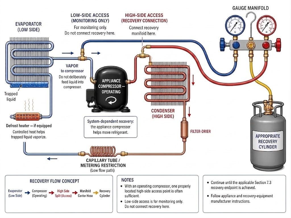
Figure 7.5.1 – With system-dependent recovery and an operating appliance compressor, refrigerant is commonly moved toward a high-side recovery connection; controlled evaporator heat can help vaporize trapped liquid.
AI-generated instructional figure: It may contain visual inaccuracies. Use the accompanying lesson text and cited authoritative sources to verify technical and regulatory details.
EPA 608 Exam Focus
Highest-Priority Fact
EPA’s current Type I test topics specifically expect:
system-dependent recovery
+
operative compressor
→ OPERATE THE COMPRESSOR
High-Side Recovery Memory Rule
For the conventional operating-compressor method:
COMPRESSOR RUNNING
→ RECOVER FROM HIGH SIDE
The reason is:
compressor moves refrigerant
LOW → HIGH
One-Fitting Memory Rule
With an operating compressor:
one properly located high-side access
→ often sufficient
Do not memorize the word:
always
Defrost-Heater Memory Rule
cold evaporator
+
trapped liquid
+
appropriate defrost heater
→ vaporize refrigerant
→ speed recovery
Recovery Endpoint Still Comes From Section 7.3
A working compressor changes the technique.
The legal endpoint still depends on the applicable current small-appliance recovery rule.
For example:
newer recovery equipment
+
functional appliance compressor
→ 90% percentage path
or:
4 in. Hg vacuum alternative
as taught in Section 7.3.
Common Mistakes and Confusing Points
Mistake 1: Turning Off a Working Compressor During System-Dependent Recovery
EPA’s current Type I test topics specifically expect the operative compressor to be operated.
Mistake 2: Recovering From the Low Side as the Standard Operating-Compressor Method
The conventional Type I system-dependent training method uses:
operating compressor
+
high-side recovery
Mistake 3: Assuming One High-Side Fitting Is Always Enough
It is often enough in the conventional method, but actual appliance configuration and manufacturer instructions control.
Mistake 4: Confusing Appliance Compressor With Recovery-Machine Compressor
If the external recovery machine provides the refrigerant-moving capability independently of the appliance:
self-contained recovery
not the system-dependent method emphasized here.
Mistake 5: Assuming the Defrost Heater Is Required on Every Appliance
Not every appliance has a defrost heater.
Use it only:
if equipped
+
if appropriate
Mistake 6: Using an Open Flame to Speed Recovery
Open-flame heating can create decomposition, fire, pressure, and refrigerant-safety hazards.
Mistake 7: Deliberately Feeding Liquid Into the Compressor
The goal is to vaporize trapped liquid and move vapor through the compressor.
Mistake 8: Stopping Recovery as Soon as Flow Slows
Slow flow can mean:
- Evaporator is cold.
- Liquid remains trapped.
- Refrigerant remains dissolved in oil.
Do not equate:
slow flow
with:
recovery complete
Mistake 9: Confusing Heat Application With a Recovery Endpoint
Heat helps refrigerant move.
It does not define legal recovery completion.
Mistake 10: Forgetting to Remove Temporary Access Fittings After Service
Section 7.4 established the current Type I exam-topic expectation that solderless access fittings should be removed at the conclusion of service.
Concept-Check Questions
Question 7.5-1
When using a system-dependent recovery device on a small appliance with a functioning compressor, what does EPA’s current Type I test-topic guidance expect?
A. Leave the compressor off.
B. Operate the appliance compressor.
C. Remove the compressor before recovery.
D. Replace the compressor with a vacuum pump.
Question 7.5-2
Why is refrigerant commonly recovered from the high side when the appliance compressor is operating during system-dependent recovery?
A. The compressor normally moves refrigerant from the low side toward the high side.
B. The high side always contains only air.
C. The low side cannot contain refrigerant vapor.
D. EPA requires two high-side fittings on every small appliance.
Question 7.5-3
Which statement about a high-side access fitting is most accurate for the conventional operating-compressor method?
A. One properly located high-side access fitting is often sufficient because the compressor helps move refrigerant toward the high side.
B. A high-side access fitting is never used on a small appliance.
C. Two low-side fittings are always required.
D. The fitting replaces the required recovery equipment.
Question 7.5-4
Why can a defrost heater speed refrigerant recovery from a refrigerator?
A. It compresses the refrigerant.
B. It cools the recovery container.
C. It warms the evaporator and helps trapped liquid refrigerant vaporize.
D. It converts refrigerant into nitrogen.
Question 7.5-5
Which is the best description of trapped liquid refrigerant during recovery?
A. Liquid remaining in cold or isolated portions of the appliance that has not yet vaporized and moved to the recovery connection
B. Water inside a recovery cylinder
C. Refrigerant that has already been reclaimed
D. Oil permanently removed from the compressor
Question 7.5-6
Which heating practice is most appropriate?
A. Use an open torch on the evaporator whenever recovery slows.
B. Use controlled heat or an appliance defrost heater when appropriate and consistent with manufacturer instructions.
C. Heat a sealed liquid-filled section as much as possible.
D. Bypass all appliance safety controls to energize the heater.
Question 7.5-7
What is the main difference between the system-dependent method in this section and self-contained recovery?
A. System-dependent recovery relies on assistance from appliance components such as the operating compressor.
B. System-dependent recovery always uses a larger recovery cylinder.
C. Self-contained recovery requires the appliance compressor to run.
D. Self-contained recovery cannot remove refrigerant vapor.
Question 7.5-8
A technician has recovered most of the refrigerant, but the evaporator remains very cold and recovery flow slows significantly. What is the best interpretation?
A. The appliance is definitely empty.
B. Liquid refrigerant may remain trapped and may need to absorb heat and vaporize before it can be moved through the compressor.
C. The technician should vent the remaining refrigerant.
D. The compressor should be flooded with liquid to finish recovery.
Answers and detailed explanations will be provided in
7.12 - Answers and Explanations.md.
Section Summary
When a Type I small-appliance compressor is functional, it can assist system-dependent recovery.
The core operating-compressor method is:
operate appliance compressor
→ pull vapor from low side
→ compress and discharge refrigerant toward high side
→ recover through properly located high-side access
The most important conclusions are:
- EPA’s current Type I test topics specifically include the need to operate an operative compressor during system-dependent recovery.
- High-side recovery works with the compressor’s normal flow direction.
- One properly located high-side access point is often sufficient when the compressor is functioning.
- This is a technique, not a separate recovery endpoint.
- The legal recovery endpoint still comes from Section 7.3.
- Refrigerant can remain trapped as liquid in a cold evaporator, oil, or other low-temperature areas.
- Controlled heat can help trapped liquid vaporize.
- A built-in defrost heater can be useful when the appliance has one and its use is appropriate.
- The goal is to send vapor, not liquid, to the compressor.
- Open-flame or uncontrolled heating should not be used.
- Temporary access fittings should be removed and the system resealed and leak checked after service.
A useful memory pattern is:
COMPRESSOR WORKS
→ RUN IT
→ RECOVER HIGH SIDE
→ WARM COLD EVAPORATOR IF APPROPRIATE
→ VAPORIZE TRAPPED LIQUID
→ VERIFY RECOVERY ENDPOINT
The next section examines the more difficult case in which the appliance compressor cannot operate.
See Section 7.6 - Recovery with a Failed Compressor.
References
Current Regulatory and EPA Sources
-
Electronic Code of Federal Regulations, 40 CFR § 82.152 — Definitions, current definitions of system-dependent recovery equipment, self-contained recovery equipment, small appliance, recover, and recovery efficiency. Accessed August 11, 2026.
-
Electronic Code of Federal Regulations, 40 CFR § 82.156 — Proper Evacuation of Refrigerant from Appliances, current small-appliance recovery endpoints, 15-pound system-dependent-equipment limit, and manufacturer-direction requirement. Accessed August 11, 2026.
-
Electronic Code of Federal Regulations, 40 CFR § 82.158 — Standards for Recovery and/or Recycling Equipment, current recovery-equipment certification framework. Accessed August 11, 2026.
-
U.S. Environmental Protection Agency, Test Topics — Section 608 Technician Certification, current Type I recovery-technique topic requiring operation of operative compressors when using system-dependent recovery equipment. Accessed August 11, 2026.
-
U.S. Environmental Protection Agency, Stationary Refrigeration Service Practice Requirements, current small-appliance recovery requirements and manufacturer-direction guidance. Accessed August 11, 2026.
-
U.S. Environmental Protection Agency, Refrigerant Recovery and Recycling Equipment Certification, current small-appliance recovery-equipment certification standards and approved testing-organization information. Accessed August 11, 2026.